Automation with Python: Power measurements using Otii
Automation with Python: Power measurements using Otii
Automation with Python makes monitoring your device’s energy consumption more efficient and streamlined. Using the Otii desktop application, you can easily monitor your device’s energy consumption and instantly see how tweaks impact efficiency. Just connect your Otii instrument to your computer, wire up your device under test (DUT), and you’re ready to go. The Otii Automation Toolbox takes it further, automating your measurements and handling repetitive tasks via a TCP-server and JSON-based API.
To make the automation setup straightforward and seamless, we’ve created pre-built TCP clients for Python, C#, Java, and Matlab. Just pick the one that fits your development environment, run your scripts, and let Otii handle the power testing and validation for you–find all the supported clients available on the Qoitech GitHub page.
Let’s quickly dive into getting started with Python automation to record power measurements and explore some practical techniques. We’ll walk through useful patterns to automatically compute energy consumption for specific segments of your device’s operation, ensuring your tests are efficient and accurate. Whether you’re performing repetitive measurements or complex validations, you’ll learn how to harness the power of Otii and Python for seamless automation.
Getting Started with Automation Using Python and Otii
To automate with Python using Otii, you’ll need an Otii Automation Toolbox license, which you can activate directly from the Qoitech User Management Portal. If you’re not ready to purchase but want to try it out, no problem—just reach out to our team to request a trial license.
Once your license is activated, and you’re logged into the Qoitech User Management in the Otii Desktop App with the license properly reserved, follow the next steps to start automating your device’s power measurements.
Setup: Otii TCP client for Python
To connect your Python program to Otii Product Suite, you’ll need the Otii TCP Client for Python, available on the Qoitech GitHub page–it is also available as PyPi package from pypi.org
Installation
To get started, install the Python client using pip:
python3 -m pip install otii_tcp_client --upgradeAfter installation, it is recommended to check if the version 1.0.10 has been installed. To confirm this, you can run the following command:
pip3 show otii_tcp_clientRunning Otii TCP Server
The Otii TCP server must be running to perform the automated power measurements. It can be enabled either via the Otii desktop app or the command line interface (CLI).
Connecting your device under test
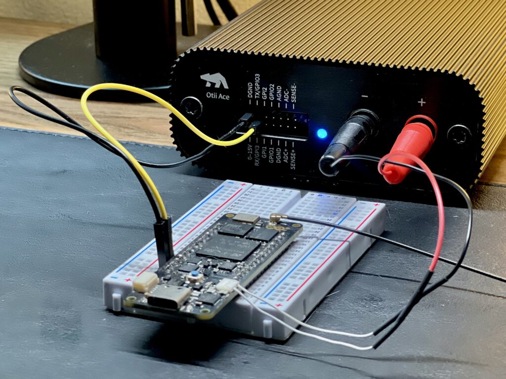
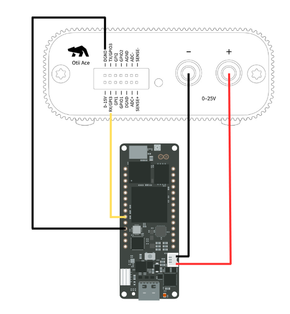
For demo purposes, in this example, we’ll measure the power consumption of an Arduino Portenta H7 connected to the Otii Ace Pro. This is where you should connect your own device under test (DUT)–just follow along, and feel free to work with your specific hardware setup.

In this setup we have:
- Connect DUT to the Otii Ace Pro via the battery/power connector using the banana connectors:
- + (positive) to the DUT’s positive battery/power connector.
- – (negative) to the DUT’s negative battery/power connector (GND).
- Connect DUT’s TX pin to the Otii Ace Pro’s RX pin to capture logs via UART.
- Connect DUT’s GND to Otii Ace Pro’s DGND–this is only necessary for the Otii Ace version since expansion port and banana connector are isolated.

Automation test setup
In this setup, we’ll power the DUT using the Otii Ace Pro while simultaneously measuring total energy consumption over time. If your device is connected via USB for programming, be sure to disconnect the USB cable before measurements–you don’t want to damage your device. Constantly disconnecting and connecting the USB while performing multiple tests can be a hassle, though—don’t worry, there’s an automated solution for that too. You can read more about how to streamline this process here.
In the GitHub repository, you’ll find a couple examples to help you get started with the Otii Automation Toolbox using the Python client. In this case, we will focus on the voltage sweep example. This particular test simulates real-world conditions as the battery discharge, by measuring how the device responds as the battery voltage decreases. It helps identify critical power thresholds, assess efficiency at different voltage levels, and detect potential issues when operating at lower voltages, which is essential for optimizing battery-driven device performance.
To compare multiple recordings made with different firmware, hardware, or setups, it’s crucial to mark the start and end of the periods you want to analyze. Typically, this includes capturing a full duty cycle—an active period followed by a longer sleep mode. Depending on your validation needs, there are different ways to do this, such as sending messages via the device’s UART, using the device’s digital output, or waiting for a falling edge.
Python code overview
The script under test automates a voltage sweep test for DUT’s power measurements. Let’s see a detailed breakdown of it:
1. Configuration: variables define the starting and stopping voltage, step size, overcurrent, UART settings, and types of conditions (messages, GPIO changes, or falling edge current detection) to stop the recording.
# Sweep settings
START_VOLTAGE = 4.2
STOP_VOLTAGE = 3.0
STEP = 0.1
WAIT_AFTER_CONDITION = 0.2

# Device settings
OVERCURRENT = 1
BAUDRATE = 115200
DIGITAL_VOLTAGE = 3.3

# Condition type
INITIAL_CONDITION_TYPE = 'message' # 'message', 'falling_edge' or 'gpio'
CONDITION_TYPE = 'message' # 'message', 'falling_edge' or 'gpio'

# Condition - wait for message
MESSAGE_TEXT = 'Entering sleep mode'
MESSAGE_POLLING_TIME = 0.2
MESSAGE_TIMEOUT = 60

# Condition - wait for falling_edge
FALLING_EDGE_CURRENT_THRESHOLD = 0.040
FALLING_EDGE_SAMPLE_TIME = 0.2
FALLING_EDGE_TIMEOUT = 60

# Condition - wait for GPI1 change
GPI1_EDGE = 'any' # 'falling', 'raising' or 'any'
GPI1_POLLING_TIME = 0.2
GPI1_TIMEOUT = 60
2. Voltage Sweep Function: it connects to the Otii instrument(Otii Ace/Arc Pro), configures channels, starts recordings, and performs a voltage sweep while monitoring for specific conditions, like a “Entering sleep mode” message.
def voltage_sweep(otii):
    '''
    This example shows how an automatic voltage sweep can be done, triggering on
    an UART message, a falling edge in current measurement or a GPI change.
    '''
    # Get a reference to a Arc or Ace device
    devices = otii.get_devices()
    if len(devices) != 1:
        raise AppException(
            f'Exactly 1 device expected to be connected, found {len(devices)} devices'
        )
    device = devices[0]

    # Set up and enable channels
    for channel in ['mc', 'mv', 'mp', 'gpi1', 'rx']:
        device.enable_channel(channel, True)

    # Set sample rate
    for channel in ['mc', 'mv', 'mp']:
        device.set_channel_samplerate(channel, 50000)

    # Configure device
    device.set_main_voltage(START_VOLTAGE)
    device.set_max_current(OVERCURRENT)
    device.set_uart_baudrate(BAUDRATE)
    device.set_exp_voltage(DIGITAL_VOLTAGE)

    # Start measuring
    print('Starting and waiting for initial condition')
    project = otii.get_active_project()
    project.start_recording()
    device.set_main(True)

    recording = project.get_last_recording()
    timestamp_condition = wait_for_condition(INITIAL_CONDITION_TYPE, recording, device)
    recording.rename('Initialization')

    print(f'Initializing done at timestamp: {timestamp_condition}')
    time.sleep(WAIT_AFTER_CONDITION)

    # Start voltage sweep
    start_voltage = int(START_VOLTAGE * 1000)
    stop_voltage = int(STOP_VOLTAGE * 1000)
    step = int(-STEP * 1000)
    for voltage in range(start_voltage, stop_voltage, step):
        print(f'\\nSetting {voltage / 1000} output voltage')
        device.set_main_voltage(voltage / 1000)
        project.start_recording()

        recording = project.get_last_recording()
        timestamp_condition = wait_for_condition(CONDITION_TYPE, recording, device)
        if timestamp_condition is not None:
            print(f'Condition {CONDITION_TYPE} found at timestamp: {timestamp_condition}')

        recording.rename(f'Voltage {voltage / 1000:.2f}')
        time.sleep(WAIT_AFTER_CONDITION)

    device.set_main(False)

    print('\\nStopping recording')
    project.stop_recording()

    print('Done!')
3. Wait Functions: the script contains helper functions (wait_for_message, wait_for_falling_edge, wait_for_gpi) to detect predefined conditions during the voltage sweep and log relevant timestamps.
def wait_for_condition(condition_type, recording, device):
    ''' Wait for a condition '''
    if condition_type == 'message':
        return wait_for_message(recording, device)

    if condition_type == 'falling_edge':
        return wait_for_falling_edge(recording, device)

    if condition_type == 'gpio':
        return wait_for_gpi(recording, device)

    raise AppException(f'Unknown condition type {condition_type}')
4. Main Execution: Connects to the Otii client, runs the voltage sweep, and manages the whole process through automated steps.
def main():
    '''Connect to the Otii 3 application and run the measurement'''
    client = otii_client.OtiiClient()
    with client.connect() as otii:
        voltage_sweep(otii)
Before running this, or any other examples available, it is recommended that you keep the following points in mind:
- For this test, we’ll connect just one Otii Ace Pro to the computer. If you have multiple Aces/Arcs, make sure to assign unique names to each one for easy identification.
- It’s recommended to set the over-current protection to 10-20% higher than the device’s maximum current draw.
- Make sure to match the UART baud rate to align with the firmware settings of the DUT. Also, confirm that digital voltage level matches the UART voltage level.
- When using the Otii Ace Pro, set the sample rate based on the time resolution you need. Higher sample rates, like 50 ksps, capture more detail but generate much larger datasets compared to lower rates, such as 1 ksps. For example, recording at 50 ksps creates 50 times more data than recording at 1 ksps.
Otii Automation Toolbox in action
In the video below, you’ll experience how the Otii Automation Toolbox works. The setup is conditioning the start and end of recordings based on an incoming UART message: ”Entering sleep mode”, sent by the Arduino Portenta H7.
In the bottom-right terminal window, you can see the code execution and real-time logs. Simultaneously, the Otii Desktop App handling power measurements, automatically decreasing the input voltage in 0.1V steps, starting from 4.2V and ending at 3V, while renaming each recording.
This example demonstrates just one approach to automation. The Otii API is highly flexible, enabling you to create custom validation routines based on your device’s requirements, from basic measurements to advanced tasks like battery emulation.
Coding resources
- Otii TCP client for Python
- Otii TCP client for C#
- Otii TCP client for Java
- Otii TCP client for Matlab
- Jenkins integration
Conclusion
Automating repetitive tasks–using Python or other supported languages, such as measurements and parameter validations, is a game-changer when developing hardware products, and it can significantly streamline your team’s workflow. With the Otii Automation Toolbox, you enhance efficiency and ensure accurate, consistent power measurements across tests. It’s perfect for tracking power usage in different scenarios, allowing engineers to quickly validate hardware performance. By automating these processes, you save valuable time and reduce the potential for errors—exactly what you need for efficient product development.
Ready to try it out? Request a free trial and experience the power of automation with the Otii Product Suite.
Become a member of our community
Gain access to exclusive resources, educational materials, and expert advice to enhance your knowledge and understanding of powering IoT devices and battery testing.