Automatic switching between debugger and power measurements
Automatic switching between debugger and power measurements
If you are performing power consumption measurements with Otii Arc Pro or Otii Ace Pro and Otii Automation Toolbox and using a debugger in your everyday work, you may want to disconnect the debugger for every power measurement. The debugger can affect the power consumption measurements significantly. Yes, the manual task of switching off/on the debugger is very annoying. That is why we have a solution for automating this unavoidable task.
We have prototyped a switchboard that you can use in your automation set-up to enable switching off/on the debugger or USB connection to your device under test automatically. The GPOs of the Otii instrument enable this automatic connect/disconnect function. You can connect your computer to your device under test, flash it, and then disconnect it from it again using a simple script.
Below, you find detailed instructions on how to use this switchboard.
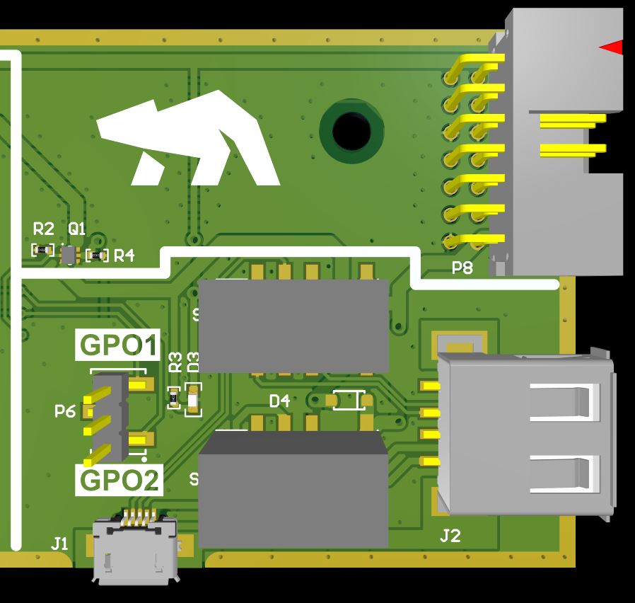
Overview of the switchboard
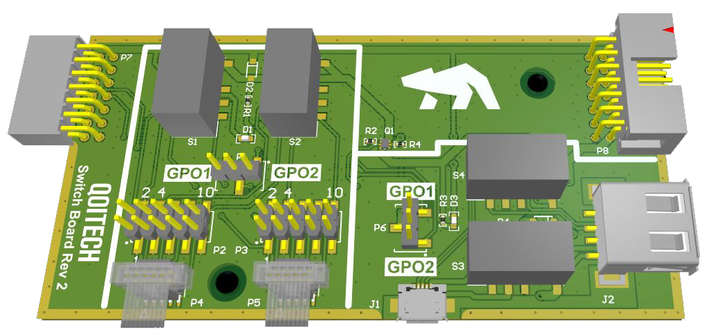
The left-side 14-pin connector is intended to be inserted into the Otii’s expansion port. All signals are passed through to the right-side 14-pin header.
All power on the switchboard comes from Otii’s +5V supply, so this needs to be switched on to make it work. Switch it on, either via script or via UI.
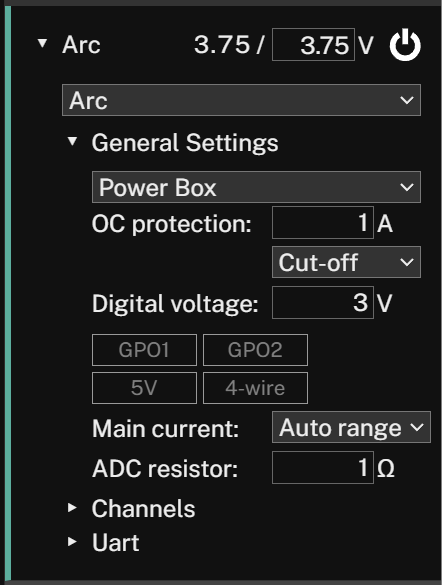
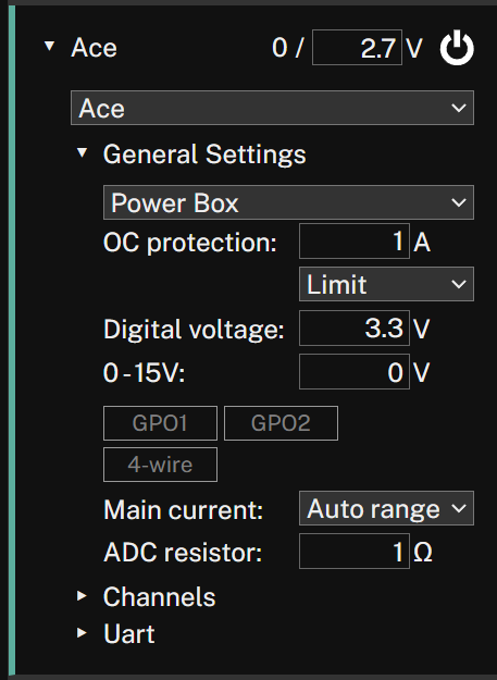
Figure 2. In Otii UI for Arc, the power is set by toggling 5V under ‘Digital Voltage.’ For Ace, 5 needs to be entered in the ‘0-15’ under the ‘ Digital Voltage.’
Programmer interface
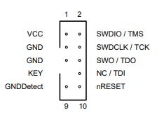
The programmer interface switches pins 1, 2, 4, and 10 of the 10-pin-header.
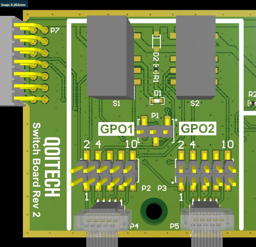
Pins 3, 5, and 9 are connected to GND; pins 7 and 8 are not connected. The 10-pin header is available as a 2.54 pitch and 1.27 pitch (keyed).
The reason for choosing 1, 2, 4, and 10 is due to the ARM Cortex debug connector where VCC, SWDIO, SWDCLK, and nRESET need to be switched.
First, choose if GPO1 or GPO2 of Otii Arc/Ace Pro will switch the relays. This is done with a jumper on the GPO1 or GPO2 side of the 3-pin header. A LED is lit when the relays are active.
USB interface
The USB interface switches D+, D-, VBUS and GND of the USB connector.
It is a micro-B connector on one side and a type-A connector on the other.
First, choose if Otii’s GPO1 or GPO2 will switch the relays. This is done with a jumper on the GPO1 or GPO2 side of the 3-pin header. A LED is lit when the relays are active.
How to script for switching the debugger
To switch the relays easily, we have prepared a Python script that can be downloaded from our GitHub.
Do you want to use the board?
Contact us if you are interested in the board. If you would like to build a similar one, check out our GitHub or our customer Irnas, who has also presented it in their GitHub. Read more about how Irnas automates power consumption measurements.